WS TuneLab – from enclosure idea to workshop drawings
An enclosure project usually starts with a practical problem. You have drivers, a limited amount of space and an idea of how the system should perform. Then come the questions: which enclosure makes sense, how much port will fit, what happens when input increases, and how will the parts actually go together? WS TuneLab brings that work into one Windows application. Develop the construction, investigate its expected behaviour and prepare the information needed to build it.
The application is for people who design and build loudspeaker enclosures, whether for their own installations or for customers. Dimensions, drivers, ports, simulations and construction parts belong to a project you can save and revisit. When a customer needs the drawings, you can create a personal enclosure passport containing the version and instructions you intend to deliver.
The useful part is following a decision through the project. A larger port changes more than the opening in the baffle. Thicker panels change more than weight. A different crossover changes more than the shape of a response curve. With the appropriate workspace and licensed module, you can investigate those consequences while the design is still straightforward to change.
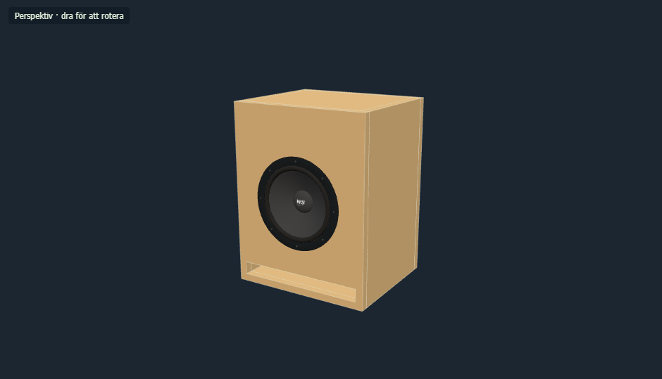
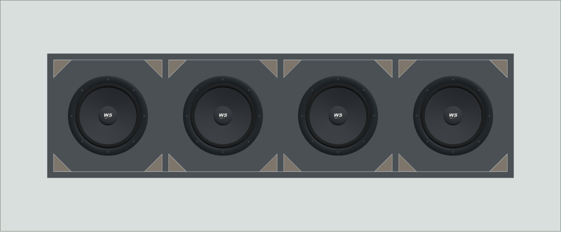
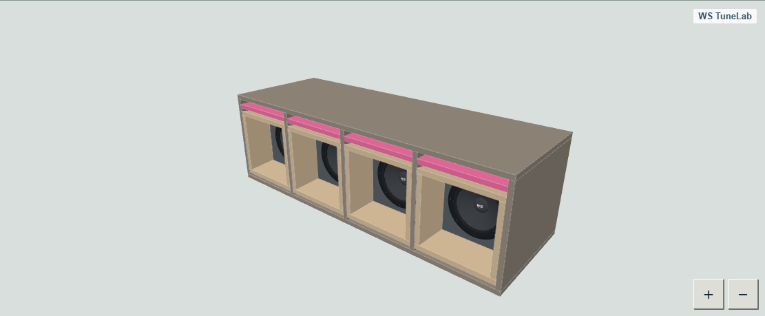
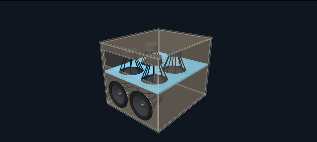
Start with the enclosure you intend to build
WS TuneLab provides workspaces for sealed, bass-reflex, bandpass, hybrid, kick and horn cabinets. There are also tools for free-form construction and a separate acoustic horn study. Each workspace presents dimensions and results appropriate to that construction. Available tools depend on the model and the modules included in your licence.
For a conventional bass enclosure, start with external dimensions and inspect how the panels, drivers and port occupy the interior. For a more involved project, work with multiple chambers, driver groups and outlets. You can choose a starting point that matches the job instead of trying to describe every enclosure with one generic set of inputs.
This is especially helpful when the available space is fixed. Compare a straightforward design with a more complex alternative and consider what the extra size and construction effort achieve. A saved project also makes customer discussions more concrete. You can show what changes between alternatives and return to the same reference without redrawing everything for the next conversation.
Driver information stays with the design
The driver is the starting point for the acoustic simulation. Choose from the driver library or work with your own information, then review the values used in the project. Acoustic parameters and mounting dimensions serve different purposes: one describes expected behaviour, while the other determines whether the physical component fits. WS TuneLab keeps both relevant to the construction.
Model name, outside diameter, cutout and mounting depth do not need to remain loose notes beside a graph. When you change drivers, review both the simulation and the physical layout. In a crowded baffle, the difference between outside diameter and cutout diameter can matter just as much as the difference between two response curves.
Missing or estimated information still needs judgement. The library speeds up preparation without removing your responsibility for selecting the correct variant. Check the impedance version and real mounting dimensions before manufacture. Discovering a mismatch in a saved design is considerably easier than discovering it after the baffle has been cut. Keep a preliminary project clearly labelled when important data still needs confirmation.
Bass reflex with room for the port and the drivers
A bass-reflex design is more than a volume and a tube. Port cross-section, length and placement must work alongside the drivers, walls and bracing. WS TuneLab treats the port as part of the construction. Supported models let you investigate round or slot ports together with the tuning you are aiming for.
Follow how a change in port area affects the required length and occupied space. An attractive acoustic idea can become awkward to build once the channel is included. Instead of discovering that during assembly, try a different arrangement, cabinet dimension or placement and compare it with the saved original. The geometry and acoustic study can inform the same decision.
Available port-air and loss tools provide further context at the intended input level. They can help identify a narrow passage, insufficient clearance or a channel consuming too much usable volume. These are questions to resolve before construction. The simulation is a design aid, not a promise that every manufactured port will remain silent under every signal or installation condition.
Keep track of bandpass and hybrid construction
Several chambers and outlets quickly become difficult to manage as disconnected numbers. The bandpass workspaces include fourth-order designs and parallel or series sixth-order arrangements. Hybrid templates provide inverted drivers with an optional front group. You can inspect the physical arrangement while working on chamber volumes, ports and drive settings.
Where separate acoustic contributions are available, compare them with the combined response. A strong result from each part does not necessarily produce the combined result you expected. Arrangement, polarity and the available phase information therefore matter alongside the individual levels. Saving a reference makes those relationships easier to investigate without losing the original setup.
Hybrid projects also support work with driver-group drive settings. That provides a more useful basis when the groups need different treatment. Save an alternative before changing several settings and return to it when necessary. The saved construction becomes a common reference for the drawing, the simulation and the next revision, rather than a collection of values you need to remember.
Kick cabinets, horn cabinets and horn studies
Kick and horn cabinet workspaces have construction tools for multiple drivers. The kick layout includes ports around the drivers. The horn cabinet provides recessed drivers, expanding mouths and supported choices for its front section and rear chamber. Three-dimensional views and construction details help you assess how the proposed arrangement will be built.
A separate horn workspace is intended for an acoustic study of horn profiles. It is useful before developing a finished construction, but it should not be confused with a complete cutting plan. A straight-profile acoustic study and a defined horn cabinet serve different stages of the job. Choose the tool according to whether you are exploring an acoustic idea or preparing a particular cabinet.
For repeated builds, saving a basic configuration helps keep comparisons consistent. Review driver count, available space, front geometry and construction information together. More specialised acoustic models still require comparison with measurements, especially when the geometry or application moves away from a simple reference case. The software helps organise that investigation rather than replacing the prototype.
Expected sound pressure with its assumptions attached
How much output is the design expected to produce, and over which frequency range? WS TuneLab can display simulated sound pressure from the project's drivers, enclosure and drive conditions. Compare alternatives before buying material or modifying an existing cabinet, and inspect where an improvement occurs rather than concentrating on a single peak value.
Keep the comparison conditions consistent. A higher line can come from more input, different filtering or a different calculation mode. Saving those settings with the project lets you return and check what you actually compared. It also gives you a clearer explanation when recommending one design to a customer instead of another.
Expected sound pressure is not a guaranteed measurement in every vehicle or at every microphone position. The reference and model limits remain part of the result. That does not make the comparison less useful: it lets you distinguish a considered design choice from an isolated high number. Save the chosen case and use it as a reference when the physical installation is measured.
Excursion, port air and electrical load
Frequency response is only part of the picture. Supported workspaces offer additional results such as cone excursion, port-air velocity, impedance, electrical input, phase and group delay. The exact selection depends on the construction. Together, these views help show the cost of a change as well as its effect on output.
One design might deliver the intended level in its working range but require more cone movement below it. A different port might change the airflow while increasing the required cabinet space. Moving between the available graphs helps identify those trade-offs and decide which part of the design deserves further attention before manufacture.
This is also useful preparation for the customer's operating instructions. Once you choose drive and filter settings, record your recommendations in the enclosure passport. The customer receives the intended setup alongside the drawings. The software does not replace amplifier specifications, actual driver limits or installation checks, but it keeps the reasoning and supporting information together.
Filters, EQ and amplification in the project
An enclosure rarely operates without signal processing. Supported tools let you investigate drive level, high-pass and low-pass filters and EQ alongside the design. Compare the effect on both response and loading, then save a sensible starting point for practical system adjustment. You can revisit the settings instead of reconstructing them from a screenshot.
Amplifier information and wiring need to reflect the intended installation. With multiple drivers, series and parallel connections form part of the operating conditions. Keeping those details close to the graphs makes it easier to avoid comparisons that look consistent but use different electrical assumptions. Grouped hybrid designs require the same attention for each group.
For example, save a reference case, introduce a protective high-pass filter and inspect where the difference appears. Then try another crossover range without changing everything at once. A saved version provides a concrete starting point for measuring and adjusting the completed installation. It does not automatically select the best amplifier or settings for every possible system.
Vehicle space and cabin loading
In a vehicle project, both physical fit and acoustic installation matter. WS TuneLab supports vehicle and installation information saved with the project. Document the available space and work with cabin geometry so that the vehicle's constraints remain part of the design process, rather than separate measurements that become detached from the current revision.
The hybrid workspace includes a coupled, simplified cabin-loading option under supported conditions. Investigate assumptions about cabin volume, door openings and leakage, and compare their effect on the estimated result. That is different from viewing an enclosure in a standalone reference environment. The application identifies the cabin mode and the relevant frequency range for the estimate.
This is not a detailed virtual replica of every vehicle. The simplified calculation does not resolve local differences between seats, microphone positions or body vibration. Its value is in comparing clearly described installation alternatives and identifying influential assumptions. Use that information to plan a prototype and measurements, with the vehicle dimensions documented alongside the enclosure.
Panel movement, material and bracing
Panel construction deserves attention alongside the acoustic design. The panel-analysis tools can estimate movement, the first field resonance and bending stress for panels the model can assess. Results can be displayed on the three-dimensional enclosure, connecting a table entry to a particular side or supported region in the actual construction.
Work with material properties, thickness and support assumptions. A before-and-after comparison helps evaluate a change, while a frequency sweep identifies movement peaks within a selected range. Thickness studies also let you compare estimated movement and material weight. This provides a more concrete basis for a decision than increasing thickness solely by intuition.
Small movement can be exaggerated visually to make it understandable. Animation gain and colour scales therefore need to be read alongside the numeric values. A dramatic shape does not mean the real panel moves by the displayed distance. Perforated and other unassessed panels are identified separately. This is a simplified construction comparison rather than certified structural verification, useful for prioritising material and bracing choices.
Three-dimensional views for practical questions
The most useful 3D view answers a construction question. Does the magnet fit? Is a passage obstructed? Where is the divider relative to the front? Inspect the enclosure from different directions and use transparent views where available. The internal arrangement becomes easier to understand before the individual parts are manufactured.
Connect that visual check with dimensions and panel drawings. A part that is difficult to judge in perspective can be reviewed separately, and its position compared with the driver's mounting data. Complex projects particularly benefit from distinguishing the outside appearance from the usable space remaining inside. Both views are necessary when a design is close to its space limit.
In a customer discussion, the model gives everyone the same construction to refer to. Show two alternatives and discuss access, placement and the extent of the build. It does not replace checking real components, cables or fixings, but it helps resolve more questions while the solution is still a change to the project rather than a change to cut material.
Free-form work when a rectangular box is not enough
Not every installation fits a simple rectangle. Free CAD and specialised shape tools are intended for projects where the available space must drive more of the geometry. Supported workspaces provide panels, angled parts, custom outlines and equipment compartments. There is also a starting point for spare-wheel-well construction.
These tools offer greater flexibility when adapting an enclosure to a vehicle or making space for other equipment. Volume, clearance, joints and assembly still need careful review. A shape that can be drawn must also be possible to build and service. Part views and manufacturing information remain important even when the outline is unusual.
Free-form tools complement the standard templates. Keep a straightforward bass-reflex project straightforward when it solves the problem. Choose a more specialised workspace when the shape genuinely demands it. You can then describe the actual design instead of modelling a conventional box and keeping a separate mental list of all its physical exceptions.
Comparisons, system projects and measurement information
Saved alternatives make development repeatable. Retain a baseline while investigating a change instead of losing the reference with each adjustment. System projects can bring together bass cabinets, midrange enclosures, horns and tweeters, explore filtering and display their combined response at a chosen point. Review each component before drawing conclusions from the total.
This shifts attention from an attractive individual curve towards the way the components are intended to work together. Document a system proposal and return to it when one component changes. Imported curves and measurement information can also be used in supporting tools, keeping measured information distinct from the calculated model rather than silently treating them as equivalent.
For recurring customer work, previous decisions become easier to follow. For a personal build, experiments become easier to repeat. Notes, project files and named versions help preserve a promising configuration so you can reproduce it after a break. When measurements become available, compare them with the documented conditions instead of an uncertain memory of the original simulation.
From design to cutting and machining
The information must work away from the screen when construction begins. Supported projects can produce cutting lists, dimensioned panel views, hole positions and PDF documents. Part references connect the enclosure overview to each individual board. That helps whether you manufacture the cabinet yourself or ask another workshop to make the parts.
DXF and CNC-related outputs are available for supported panels and workflows. They provide input for machining preparation. Tool selection, compensation, workholding and machining order still belong to the actual machine and material process. A useful export clarifies the transition from design to manufacture without pretending to replace the workshop's checks.
Use the printout as a final project review. Check quantities, thicknesses, openings and angles against the saved construction. Clear version names matter when several people are involved. They help distinguish an early proposal from the approved cutting information and make it easier to answer a question about a specific part without guessing which drawing someone is holding.
A clearer handover through enclosure passports
The licensed designer works in the Windows application. The customer does not need to buy the program to receive their drawings. Create a passport from a saved project, enter the customer's email address and add the instructions you want to provide. The customer then accesses their personal documents through the website.
A passport can contain an enclosure overview, dimensioned parts, saved curves, history and your operator notes. Add numbered assembly steps and recommendations for crossover, filtering, amplification and wiring. These are your instructions, allowing you to tailor the handover to the cabinet and the customer's installation rather than supplying generic advice.
The delivered snapshot is separate from your continuing working project. Developing the next revision does not automatically replace the customer's original. That gives the business a clearer record of delivery and the customer a consistent reference. Printing provides an overview and part dimensions for the workbench, while the online passport keeps the supporting material together for later use.
Use the tools the project needs
WS TuneLab supports both straightforward first projects and more involved development. Select the construction, collect suitable data, compare relevant alternatives and save a considered result. Licence modules determine the available tools. Monthly, annual and trial licences are managed separately from this website; the site has no subscription checkout.
You do not need every feature for every enclosure. Use dimensions and 3D when the question is physical space. Review drive and graphs when the question is loading. Use the applicable panel tools when the question concerns the boards. Once the construction is ready, prepare the manufacturing information and deliver the correct version.
For a workshop handling several customers, organisation matters as much as the calculation. Repeated designs can begin from the correct baseline, special projects can have their own instructions, and a customer's question can be linked to the drawing actually delivered. The designer handbook explains the workflow in more detail. The download page identifies available Windows releases. Together, these resources help you decide which tools fit your work before moving from design to a physical build.
Keep the completed project as a reference for the next job. A documented design can be reviewed, compared and improved without losing the information that made the first version useful. That continuity matters when a one-off experiment becomes a repeat build or when a customer returns with another installation to develop.